Easy controller, Compact controller

Easy controller, Compact controller

TROX UNIVERSAL controller,
TROX LABCONTROL controller

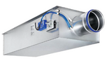
Circular connection on the fan end

Rectangular connection on the room end
Tested to VDI 6022
VAV terminal units for extract air control in buildings with variable air volume systems and demanding acoustic requirements
■ Highly effective integral attenuator
■ Box style construction for the reduction of the airflow velocity
■ Electronic control components for different applications (Easy, Compact, Universal, and LABCONTROL)
■ Closed blade air leakage to EN 1751, up to class 4
■ Casing air leakage to EN 1751, up to class C
Optional equipment and accessories
■ Acoustic cladding for the reduction of case-radiated noise
■ Secondary silencer Type TS for the reduction of air-regenerated noise
Nominal sizes
125, 160, 200, 250, 315, 400
VariantsAccessories
Useful additions
Closed blade air leakage:
Maintenance
Disclosure of Chemicals
RoHS EU Directive 2011/65/EU (RoHS)This product or individual variants comply with EU Directive 2011/65/EU (RoHS) on the restriction of the use of certain hazardous substances in electrical and electronic equipment. For more information, please refer to our Environmental Product Declarations. REACH 1907/2006 (EC Regulation REACH)This product or individual variants comply with the provisions of EC Regulation No. 1907/2006, also known as REACH (Registration, Evaluation, Authorisation and Restriction of Chemicals). For more information, please refer to our Environmental Product Declarations
1 Integral sound attenuator
2 Double lip seal
3 Damper blade
4 Effective pressure sensor
5 Control components, e.g. an Easy controller
Nominal sizes | 125 – 400 mm |
Volume flow rate range | 14 – 2007 l/s or 50 – 7228 m³/h |
Volume flow rate control range (unit with dynamic effective pressure measurement) | Approx. 10 – 100 % of the nominal volume flow rate |
Minimum differential pressure | Up to 258 Pa (without circular silencer) |
Maximum differential pressure | 1000 Pa |
Operating temperature | 10 to 50 °C |
| TVA | – | D | / | 160 | / | D1 | / | Easy |
| | | | | | | | | | | ||||
| 1 | 2 | 3 | 4 | 5 | ||||
No entry: none
D with acoustic cladding
3 Nominal size [mm]D1 Double lip seal (one end)
5 Attachments (control component)Easy Volume flow controller, dynamic, analogue interface, setting of qᵥmin and qᵥmax with potentiometers (provided on site)
| Acoustic cladding | Yes |
| Nominal size | 400 mm |
| Attachments (control units) | Easy controller, dynamic, analogue interface, Adjustment qvmin and qvmax with potentiometers |
Share page
Recommend this page
Recommend this page by sending a link by mail.
Share page
Thank you for your recommendation!
Your recommendation has been sent and should arrive shortly.
Contact
We are here for you

Please specify your message and type of request
Tel.: +49 (0)2845 / 202-0 | Fax: +49 (0)2845/202-265
Contact
Thank you for your message!
Your message is send and will be processed shortly.
Our department for Service-Requests will contact you asap.
For general question regarding products or services you can also call:
Tel.: +49 (0)2845 / 202-0 | Fax: +49 (0)2845/202-265
Contact
We are here for you
Please specify your message and type of request
Tel.: +49 (0)2845 / 202-0 | Fax: +49 (0)2845/202-265
Contact
Thank you for your message!
Your message is send and will be processed shortly.
Our department for Service-Requests will contact you asap.
For general question regarding products or services you can also call:
Tel.: +49 (0)2845 / 202-0 | Fax: +49 (0)2845/202-265